

RESISTORS
Purpose
Simply put, resistors restrict the flow of electric current.
Measurement
Resistance is measured in ohms, the symbol for ohm is an omega ![]() . Resistor values are often represented in k
. Resistor values are often represented in k![]() and M
and M![]() , where 1 k
, where 1 k![]() = 1000
= 1000 ![]() and 1 M
and 1 M![]() = 1000000
= 1000000 ![]() .
.
Color Codes |
|
| Color | Number |
| xxx | |
Resistor color code
Resistor values are normally indicated using colored bands. Each color represents a number as shown in the table.
Most resistors have between 4 and 6 bands:
- The first band gives the first digit.
- The second band gives the second digit.
- The third band indicates the number of zeros.
- The fourth band is used to indicate the tolerance (precision) of the resistor. A special colour code is used for the fourth band tolerance:
- silver ±10%, gold ±5%, red ±2%, brown ±1%.
If no fourth band is shown the tolerance is ±20%. - Example: a 220k
 resistor with a tolerance of ±10% will have a value within 10% of 220k, that is between 220 - 22 = 198k and 220 + 2 = 242k .
- silver ±10%, gold ±5%, red ±2%, brown ±1%.
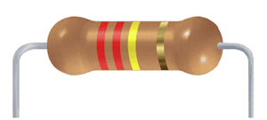
This resistor shown has red (2), red (2), yellow (4 zeros) and gold bands.
So its value is 220000 ![]() = 220k
= 220k![]() .
.
Here is a great link to a 6 band resistor calculator on EE Web (Electrical Engineering Community)
Resistors in Series
When resistors are connected in series their combined resistance is equal to the individual resistances added together. For example if resistors R1 and R2 are connected in series their combined resistance, R, is given by:
Combined resistance in series: R = R1 + R2
This can be extended for more resistors: R = R1 + R2 + R3 + R4 + ...
Resistors in Parallel
When resistors are connected in parallel their combined resistance is less than any of the individual resistances. Use the following equation for the combined resistance of two resistors R1 and R2:
| Combined resistance of two resistors in parallel: |
R = | R1 × R2 |
| R1 + R2 |
For more than two resistors connected in parallel a more difficult equation must be used. This adds up the reciprocal of each resistance to give the reciprocal of the combined resistance, R:
| 1 | = | 1 | + | 1 | + | 1 | + ... |
| R | R1 | R2 | R3 |
Fixed Resistors in Guitar Circuits
- Treble Bleed Circuit
One of the most common applications of fixed resistors in guitar circuits is in treble bleed circuits (aka volume kits). A volume kit is a very simple mod that will prevent the loss of highs as you roll down your guitars volume control. Many pros will recommend slightly different methods on how to achieve this. After much research I have settled on a 150K resistor in parallel with a small capacitor in range of 680 pf - 1000 pf.
- Reducing the Value of a Variable Resistor (Pot)
Let's say you need a 500k pot for a guitar application but you only have a 1 meg pot available? You can change the 1 meg pot to be used as a 500k pot by placing 1 meg resistor in parallel with the pot (that is across both outside terminals of the pot).